
Intrinsic safety Ex i: principle and uses
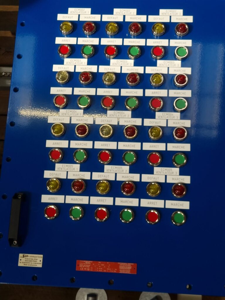
Intrinsic safety, marked Ex i, does not try to contain an explosion like the Ex d flameproof enclosure. It limits the electrical and thermal energy of a circuit to a level too low to ignite the atmosphere, even in the event of a fault. It is defined by the EN/IEC 60079-11 standard.
Three levels of protection
| Level | Faults taken into account | Zones of use |
|---|---|---|
| ia | Safe with two faults | Zones 0, 1, 2 (and 20, 21, 22) |
| ib | Safe with one fault | Zones 1, 2 (and 21, 22) |
| ic | Safe in normal operation | Zone 2 (and 22) |
For which equipment?
Ex i suits low-power circuits: sensors, pressure or temperature transmitters, detectors, signalling buttons, 4-20 mA loops, fieldbuses. It is not suitable for power, such as supplying a motor or lighting.
Barriers and isolators
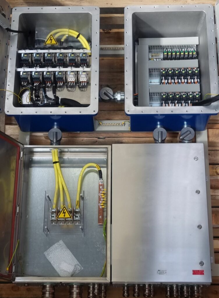
On the safe-area side, associated apparatus limits the energy sent into the hazardous area: a Zener diode barrier or a galvanic isolator. It is marked in square brackets, for example [Ex ia Ga] IIC. The designer checks that the sensor, cable and barrier together respect the voltage, current, capacitance and inductance parameters of each element.
Ex i and enclosures
In the hazardous area, Ex i circuits are often grouped in a junction box in Ex e increased safety. They are then separated from other circuits and marked in light blue: terminals, cables, labels. Our design office builds these separation and marking rules in from the design stage.
Advantages and limitations
- Wiring and maintenance possible while live, depending on site rules.
- Light equipment, without a heavy enclosure.
- Very low available power.
- The whole loop must be calculated.